|
©Copyright
1997-2010
Johnson
Kinetics, Inc.
All
Rights Reserved
Pages
best printed
in
Landscape
|
|
ElectroTactile Stimulation
ElectroTactile Stimulation allows a person to
feel a very wide range of sensations, from just-noticable to warm-fuzzy
to attention getting to pain. Nerves are stimulated directly without
any harm, even on the most dramatic settings. JKI has developed its
ETS product capability to producing the many effects possible for a variety
of applications.
| This page features ElectroTactile
Stimulation (ETS) hardware and details specifications and options of JKI's
family of custom built devices.
JKI Introduces the TacWave
Line of Tactile Stimulator Drivers. TacWave includes both Vibro and Electro
Tactile Systems. |
| If you would like General Information on Tactile
Stimulation (Both ETS & VTS), please visit our Tactile Section. |
 |
|
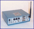
TacWave
ETS Drivers:
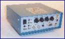
| Two medium output configurations are
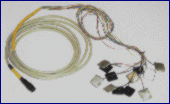
shown to the right. Model 204A has 48 outputs in 4 groups
of quick-connected cables. Several different Arrays can be
connected at the same time. All TacWave ETS Drivers work with all
ETS Arrays shown below. Inputs for manual control, dual kill switches,
internal/external grounds, operating mode inputs, and standard LED status
indicators are standard. RF telemetry control is optional. |
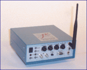 |
| A High output configuration is shown
to the right. Model 212C has 108 total outputs; 36 channels
in three groups of quick-connect and 72 channels in three sets of DIN cables
( built specifically for high count vests ). Inputs for manual control,
dual kill switches, internal/external grounds, dual operating mode inputs,
self testing of status of cable indicators, and standard LED status indicators
are standard. RF telemetry control is optional. |
 |
TacWave ETS Driver Special Features:
-
Manual, PC, Automated, Closed-Loop Control Options
-
Units use a dedicated pulse train / waveform generator
and can synthesize any pattern through on-board or controlled means
-
Wide channel count ( minimum of 4 Ch ) in custom
applications
All ETS Drivers Include:
| Quick-Connect 12 Channel Ports |
Grouped I/O Connectors |
| (2) Triple-Acting Kill Switches |
Operating Mode Select |
| External Power Supply |
High Impedance Communication |
| Isolated Internal Power Converter |
16 Embedded Patterns |
| Ground / Isolation Mode |
Use and Care Manual |
| Front Panel Operation / Status
LEDs |
TSComm Prototcol Description |
| Desktop / Rack Mount Enclosure |
Dedicated Waveform Generation |
ElectroTactor Driver Options include:
| Mapped Input Sensor Processors |
Internal Battery Operation |
| Multi-Port I/O Connectors |
Additional Embedded Patterns |
| RF Telemetry / Control |
Cascaded Operation |
| Self Instrumentation Output |
Multi-Driver Synchronization |
| Reduced Function Controllers |
Presentation / Carry Case |
ETS Driver Enclosure Specifications:
| Number of Tri-Polar Output Channels |
| Any Other Outputs (relays, open
drain, timing, etc. ) |
| Typical Array Outputs ( 2x12, 48,
etc. ) |
| Alternative Inputs ( Sensors, Control,
Digital, Serial, etc. ) |
| Size / Weight Requirements ( if
any ) |
| Enclosure Type (Miniature, Metal,
Plastic, Rack Mount etc.) |
| Typical Method Control ( PC, MCC,
Handheld, Panel, etc.) |
| Any other Special Features ( High
'G', Waterproof, etc. ) |
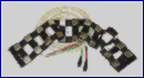
ElectroTactor Arrays.
Choose from these configurations or specify your
own according to your prospective mapping / applications including vests,
forearm, soles, neck, finger, and others.
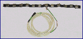 12 Ch. Radial Belt
(1 Rows of 12, Tin Tactors Shown) |
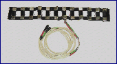
24 Ch Radial Belt
(2 Rows of 12, Tin Tactors Shown) |
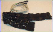
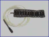
24 and 36 Tactor Belt
(2/3 rows of 12, 24 Ch. Shown) |
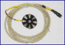
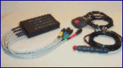
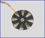 9 Ch Small Circle
(Tin Tactors Shown) |
12 Ch. Strip
(Cond. Rubber Tactors Shown)
|
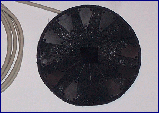
12 Ch Medium Circle
(Conductive Rubber Tactors
Shown)
|
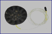
13 Ch Large Circle
|
3x4 12 Ch Grid
(Intended for Leg / Back)
|
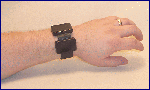
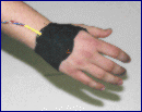
4Ch Wrist Mount
(Communication Example) |
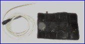
12 Tactor Garmentless
(Can be arranged with velcro/tape) |
Support Accessories
(Tactor Pattern Simulators, Kill
Switches) |
|
ETS Array Specifications:
| Size and Range for Flexible Garment Based Arrays |
| Verify the Total Channel Number |
| Connectors (with respect to your Driver I/O) |
| Cable Length / Strain Relief (if needed) |
| Rubber, Tin, Silicone, Gel, or Electrode Based
Tactors |
| Tactor Area and Shapes (square, circular, wedge,
etc. ) |
TacWave Controllers:
All TacWave, ETS, VTS, and LSAC systems can be
controlled through the TSComm protocol. This protocol is built into
our line of Manual Control Consoles (MCCs), Hand Controllers (HCs), and
can be generated by a computer's serial or USB port.
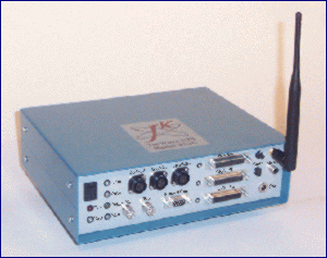
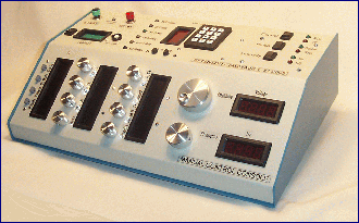
| This Manual Control Console( MCC ) unit was designed
for test and experimentation, as shown to the right. It features
isolated TSComm Syntax communications with a TacWave ETS Driver, multiple
LED displaces and indicators, separate adjustment for many primary settings,
adjustments for embedded patterns, alpha-numeric keypad, and multiple operating
modes. The desktop unit also included a built in timer to control
timed responses to mapped stimuli. A similar reduced function unit
is being built for more portable applications. |
 |
MCC Special Features:
-
Timed self monitoring of the ETS driver to insure
communications
-
Auto shutdown based on critical settings, responses,
or kill switch activation
-
Buffering for PC Control/Response and Instrumentation
Lines
-
Adaptable settings control for embedded patterns
Configuration control for various/ multiple Tactor
Arrays
//
|
|